Lidar and PX4Flow mounting
To mount these parts on the frame you will need:
- A drill with a set of common drill bits (2-4 mm diameter)
- A soldering station with a nice third-hand and some heatshrink
- M3x10 button socket head cap screws (same ones are already used on Iris+) - available for example from here
- M3x0.5 hex nuts, available here
- Electrical or Kapton tape
- A 4-pin DF13 cable
Let’s start!
- Remove the top cover of the Iris+. You will need to unplug the RC radio, the magnetometer and maybe a couple of other things. Make sure to note the location of anything you unplug for reassembly later.
- Remove the bottom cover. You will need to unplug the I2C LED and unscrew the USB port
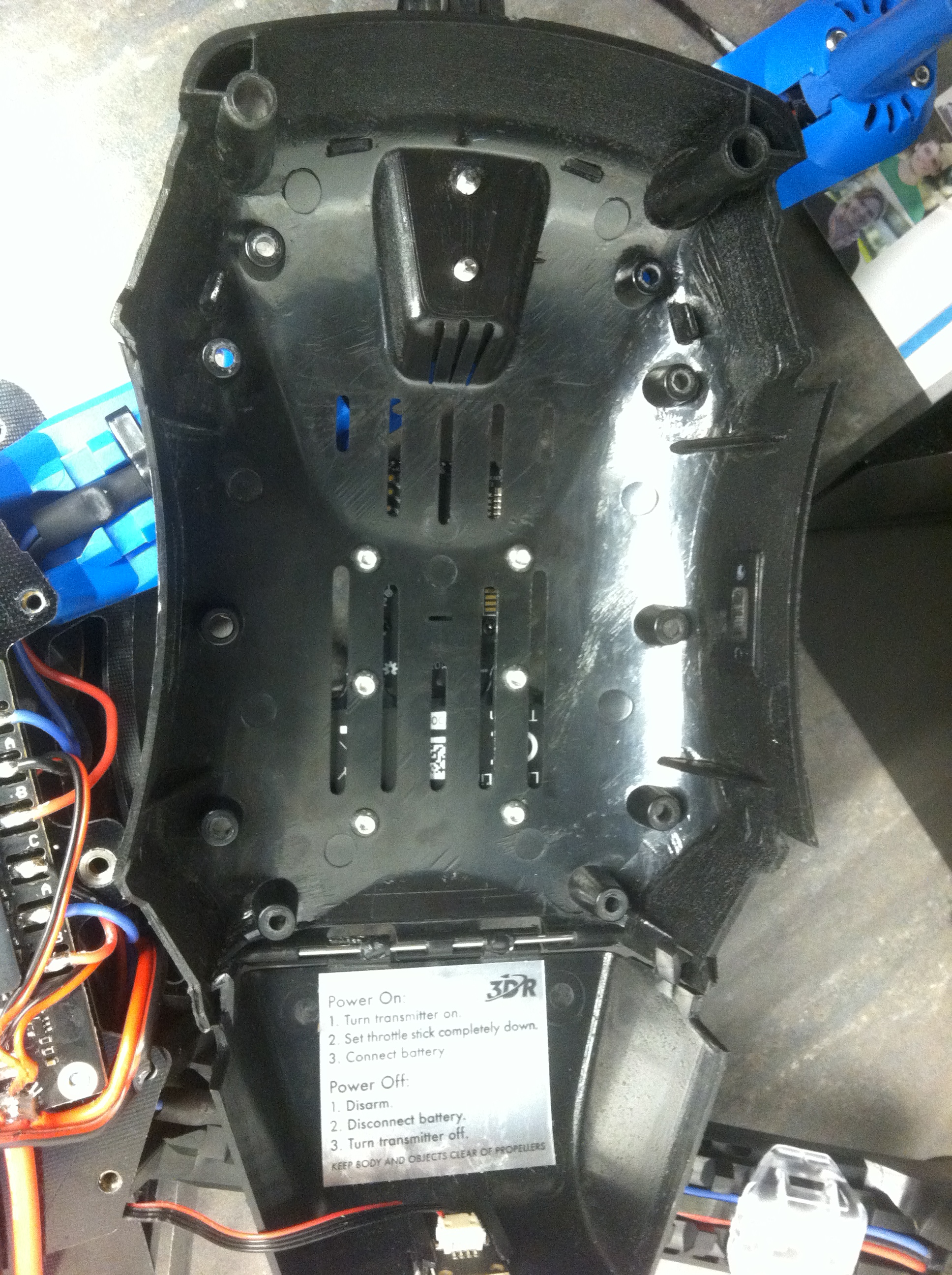
- Put the bottom cover flat. Optionally remove the battery bay door. Place the PX4Flow and the lidar as shown in the picture below. Orient the lidar with its connector facing towards the battery bay door, the PX4Flow with the camera closer to the bay door, and the sonar closer to the camera mount.
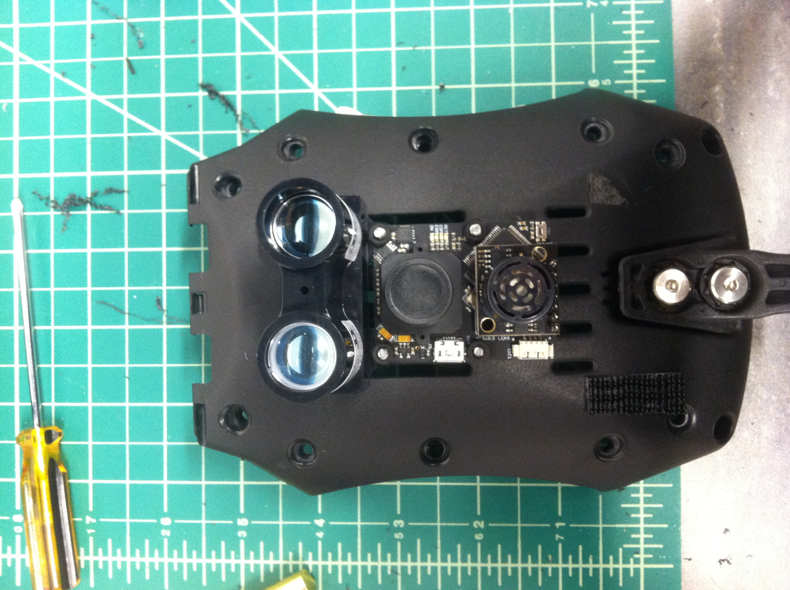
Sensors orientation
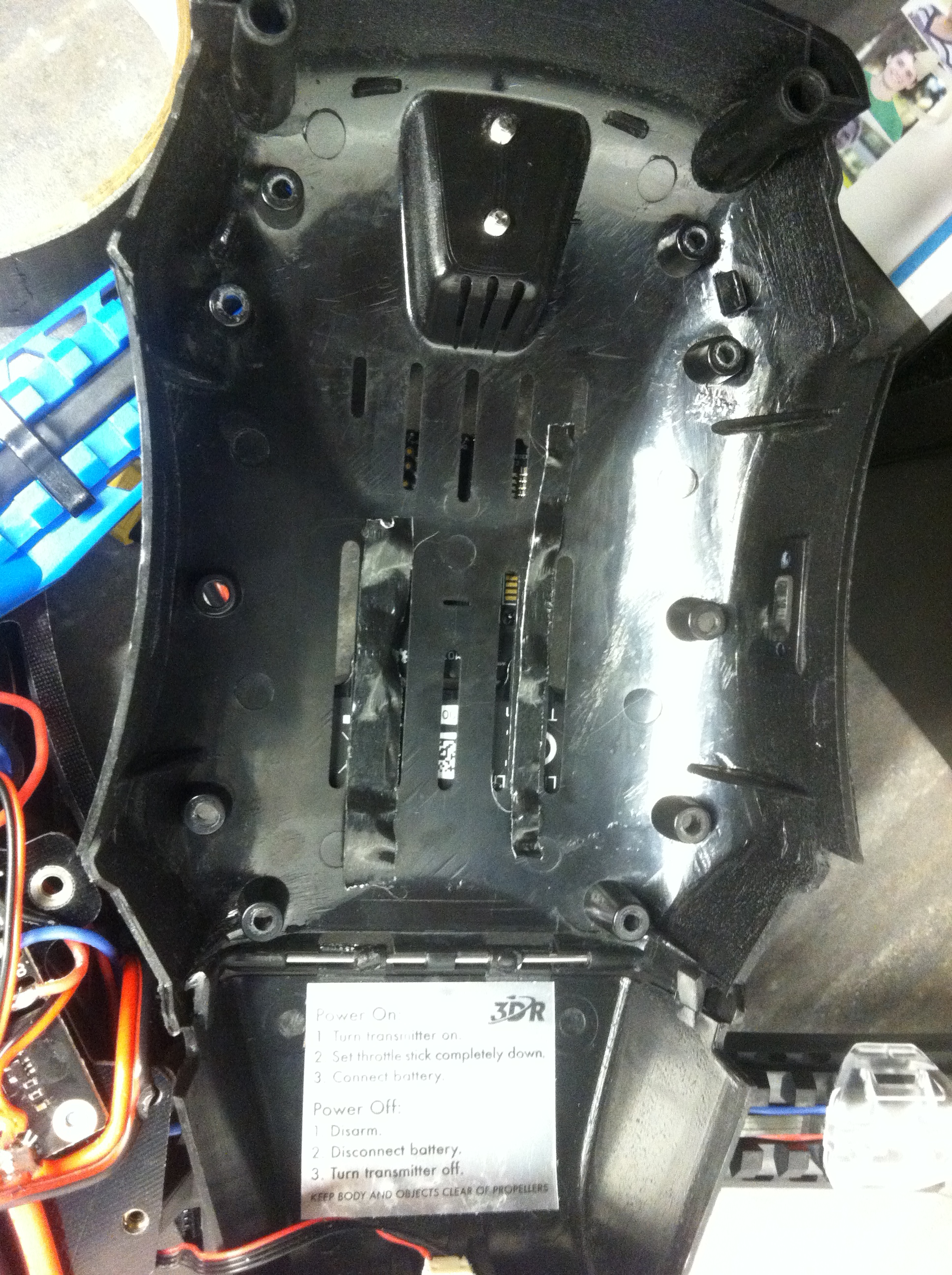
- We want to place both sensors on the flatter part of the belly, just before it starts tapering down towards the camera holder:
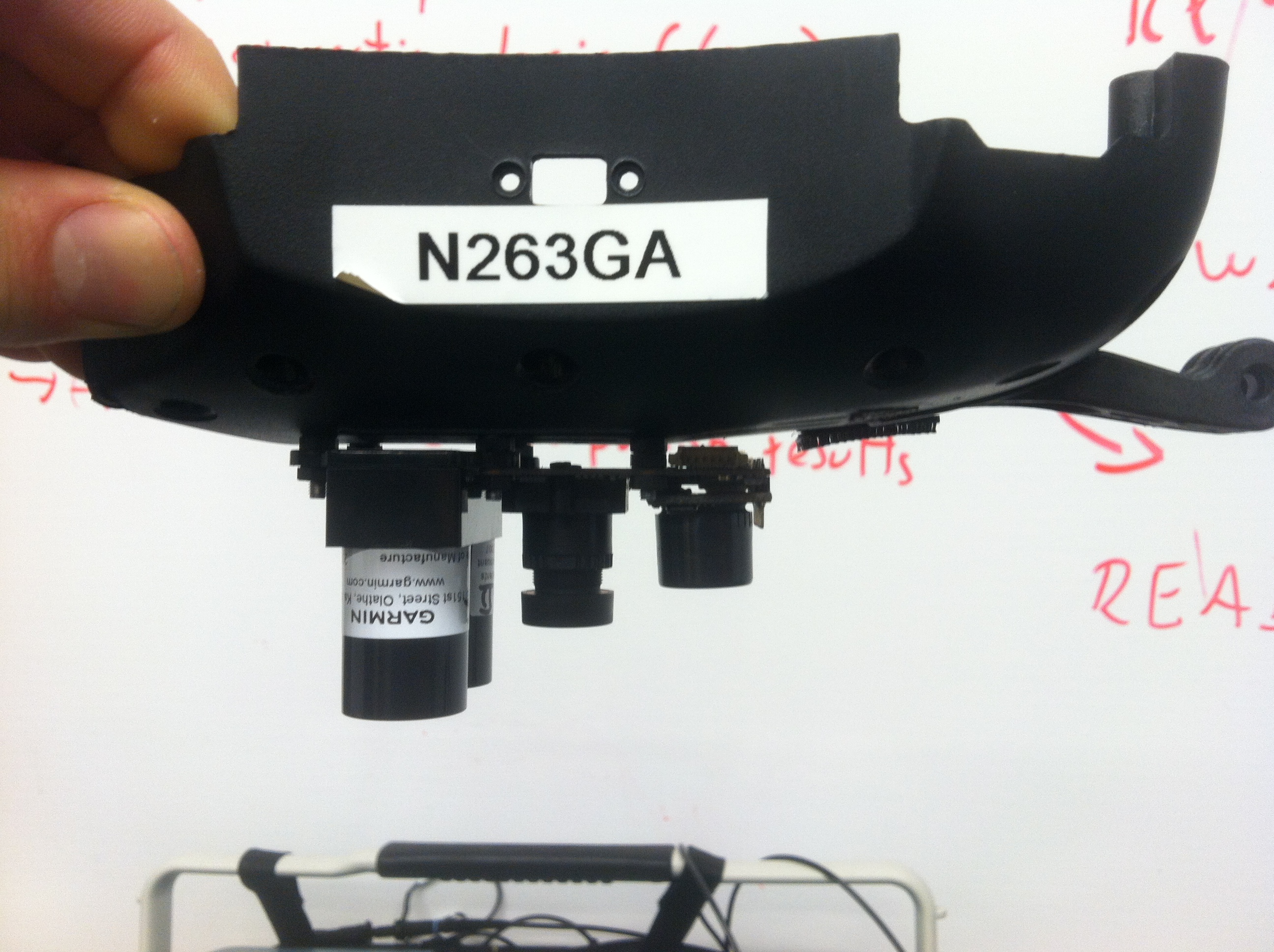
Sensors placement
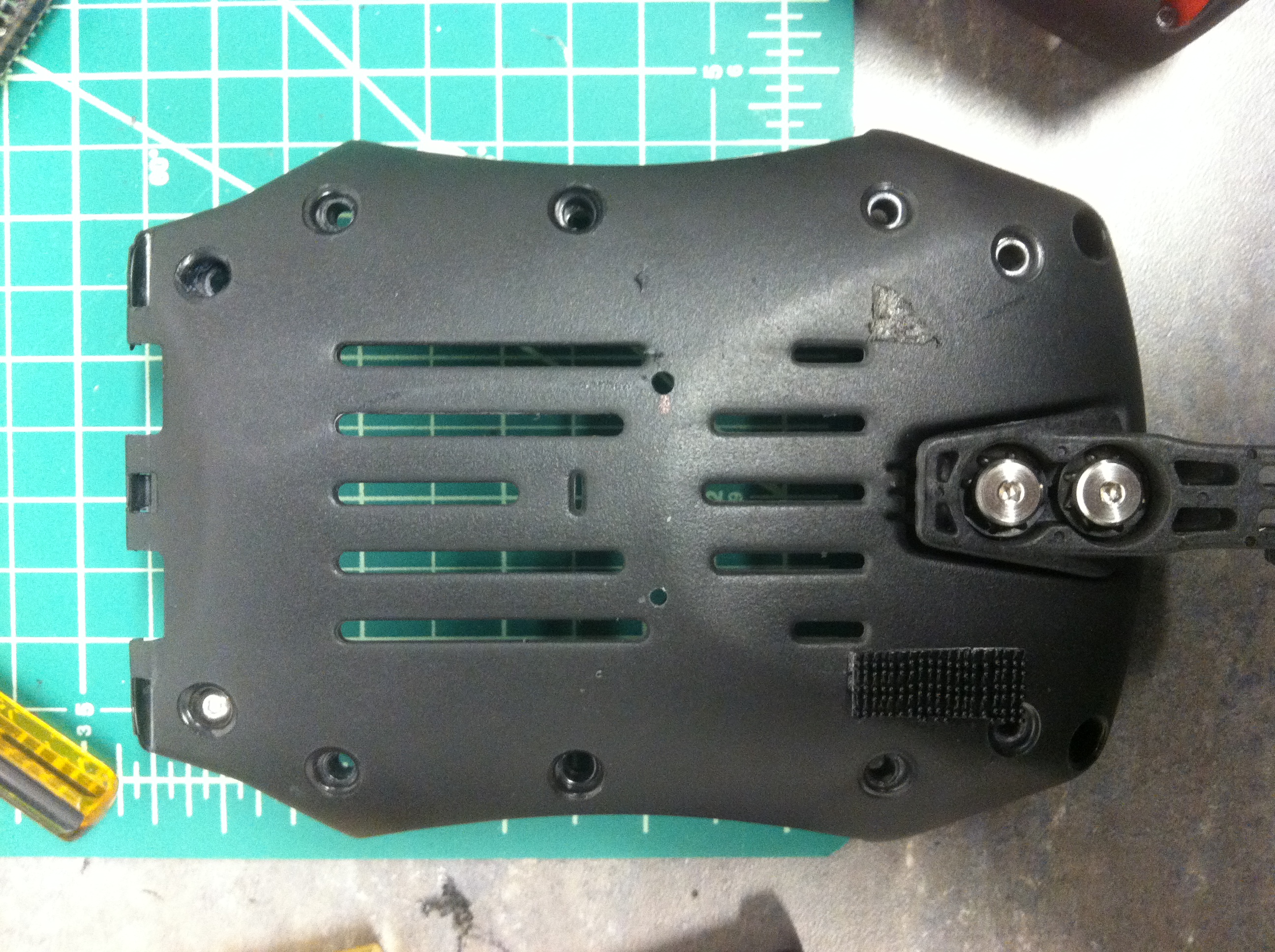
- The lidar and the PX4Flow camera share two mounting holes. We will drill 6 holes total, following the layout of the sensors:
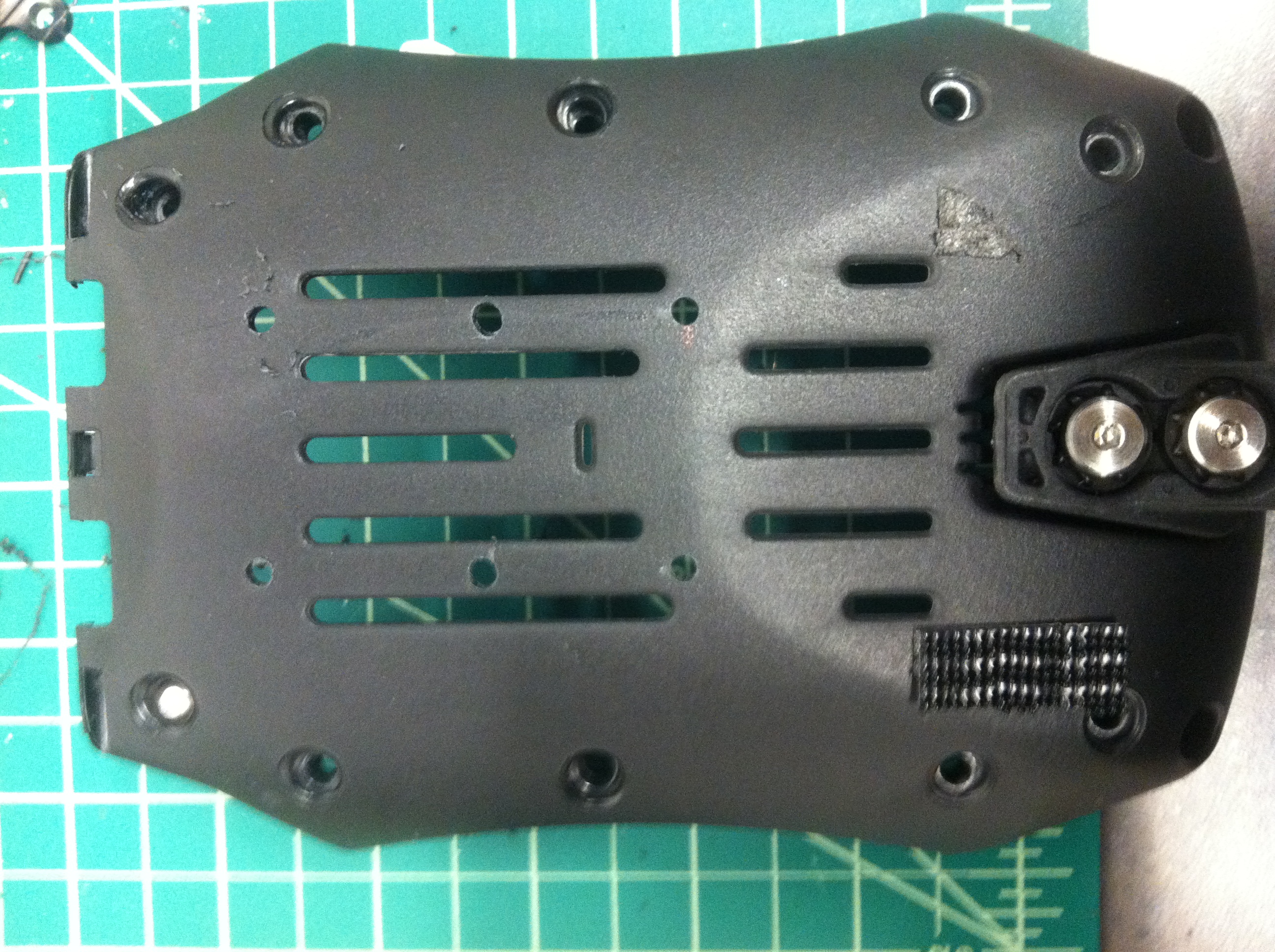
Holes placement
- We recommend using a small marking bit to mark the location of the holes (you can use tape to hold the sensors in place), and then drilling final holes for M3 screws with a larger drill bit. Here is an illustration of the process; the smaller guide hole is on the bottom, larger final one is on the top:
Drill small hole first, then use a bigger bit
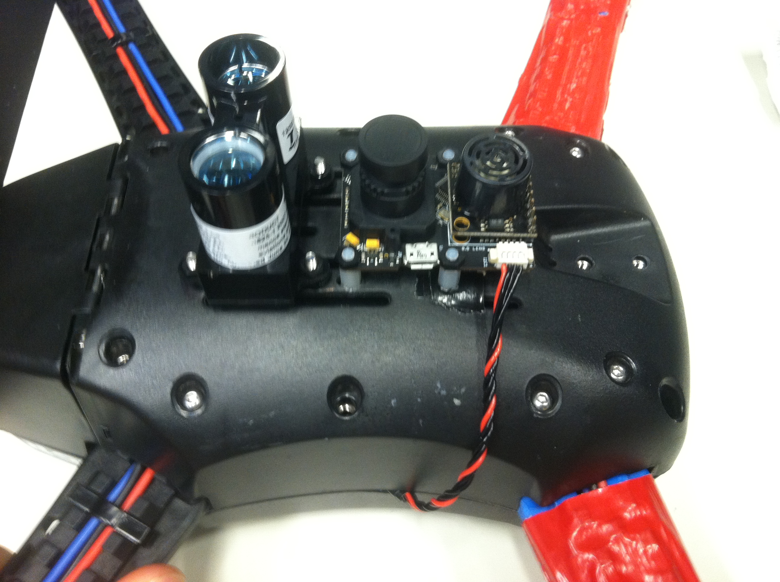
- Now mount the sensors. The screw head will be inside the frame, and the nylon nuts are on the sensors side. You will need to use multiple nuts to give the sensors enough space so they don’t touch the plastic directly.
Sensors mounted - view from inside of the frame
- Use a thin slice of tape to cover the screw heads in the inside. There is enough clearance from the capacitors on the ESC board, but we don’t want to take any chances here:
Covered screw heads, just in case
- Now we need to add the I2C cable to connect to the PX4Flow. We have to cut a little notch in the top cover so we don’t pinch the cables:
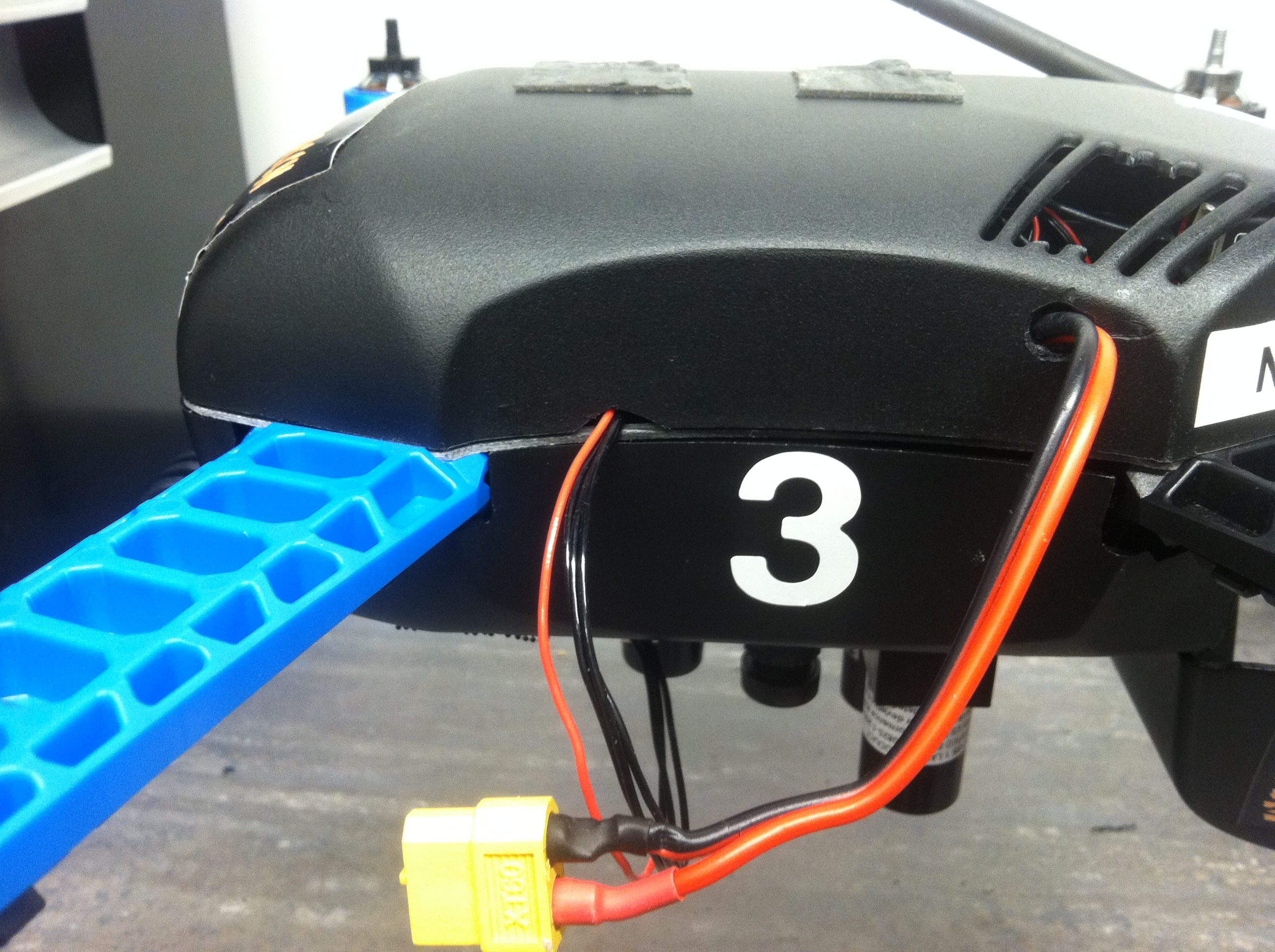
Cut a small notch for the cables
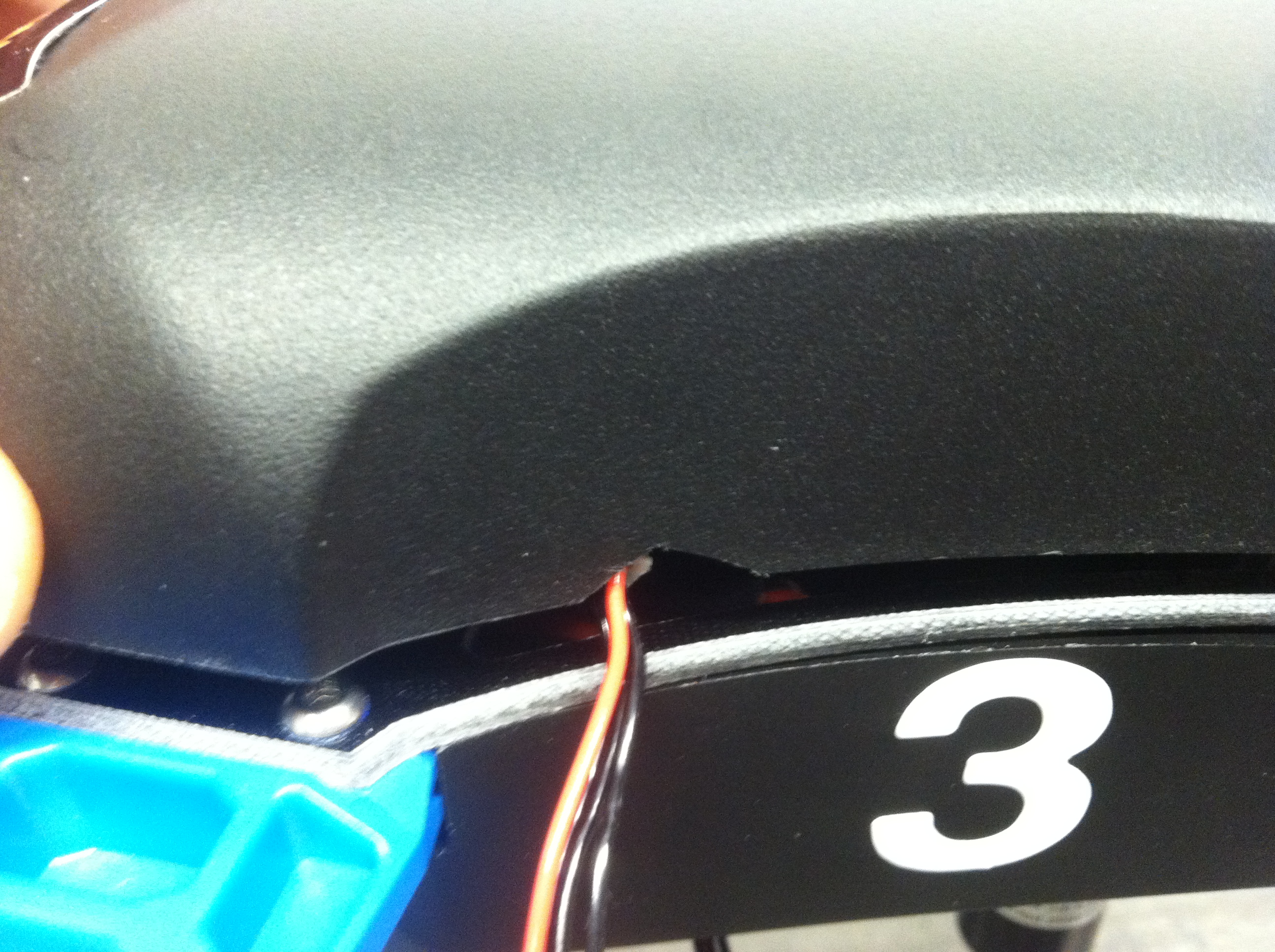
Detail of the same
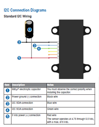
- Now it is a good time to solder the lidar cable. Get the lidar cable and a 4-pin DF13 I2C cable. Cut the I2C cable in half, since we will need to solder it to the lidar cable. We need to connect:
- Lidar red -> PX4 red (VCC)
- Lidar black -> PX4 pin#4, furthest away from the red (GND)
- Lidar Green -> PX4 pin#2 next to the red (SCL)
- Lidar Blue -> PX4 pin#3 (the last one free) (SDA)
The third hand comes in handy here. Use some heatshrink to protect the solder joints. Once you have the cable ready, connect it to the lidar on one side and to the I2C splitter on the other. Below are the pinouts:
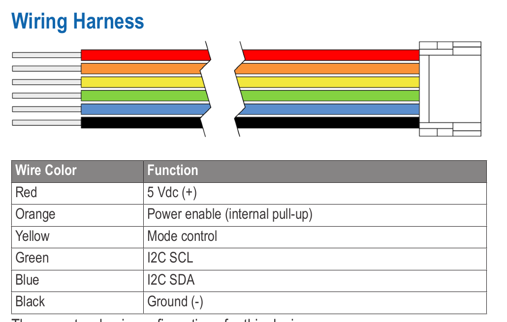
Lidar lite wiring harness
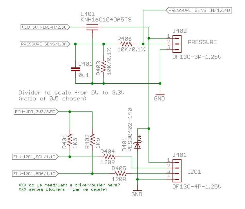
Pixhawk I2C connector (for reference)
- Finally, don’t forget to twist all the cables to cut down on unwanted noise.
Twisted i2c cable
And that is it!
Final notes
If your lidar doesn’t initialize properly at each power-up, you might need to add a large capacitor ~1000uF at the power rails (as described in Sparkfun discussion):
Lidar capacitor