Sensor calibration
Theory
Accelerometer and Magnetometer calibration is critical to the performance of the attitude and heading estimation algorithm and can be performed without special hardware. The gyroscope doesn’t have to be calibrated, because we are estimating its bias at runtime. For the magnetometer, it is very important that the calibration be performed in the fully assembled vehicle with all systems powered on. This is called hard-iron calibration and will allow us to compensate for any constant parasitic magnetic fields generated by the vehicle. The accelerometer calibration on the other hand should be performned only with the Pixhawk board, before it is integrated in the vehicle.
The calibration process consists of finding a set of neutrals and scale factors for each sensor, such as
More details about the theory can be found at Paparazzi Wiki.
Accelerometer calibration
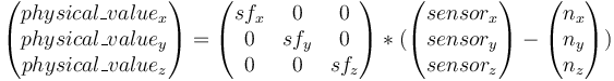
The principle of the calibration is the following: an accelerometer, on a vehicle at rest, measures a constant vector (the opposite of gravity) in the earth frame, expressed in the vehicle frame. Written down this looks like:
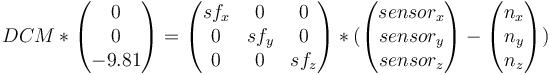
DCM is a rotation matrix that converts between earth frame and body frame. It will change when we change the orientation of the vehicle. Nevertheless, a rotation conserves the norm of a vector, so we can obtain the following scalar equation that doesn’t depend on the vehicle orientation:

Where 9.81 is the earth’s average gravity value. We can then record a number of measurements in different orientations and find the set of scale factors and neutrals giving the norm closest to the average gravity value. Again, more details can be found at the Paparazzi Wiki.
Preparation
It is very important to align the gravity vector with each of the accelerometer axes (not the body axes of the airfame). Even a small imperfection in the calibration can lead to a few degrees offset in the orientation estimate, so be very careful and follow the instructions precisely.
If you have the Pixhawk mounted in the Iris+ (which you probably have):
- Download these two files from Paparazzi autopilot project: calibrate.py and calibration_utils.py and save them to
smaccmpilot-stm32f4/src/ivory-px4-hw/test-client/calibration/. (We cannot include these files in the SMACCMPilot repositories since they are GPL-licensed). You may need to install the Pythonscipyandmatplotlibmodules for these scripts to work, e.g.,pip install scipy matplotlib. Apply the patch file for
calibration_utils.py:$ cd smaccmpilot-stm32f4/src/ivory-px4-hw/test-client/calibration $ patch < calibration_utils.patch- Open Iris+ airfame
- Unplug all connectors from the Pixhawk
- Unscrew the top of the Pixhawk
- Unscrew the PCB inside (NOTE: remember position and orientation of the servo connectors in the back of the board before you unplug them)
- Place the Pixhawk PCB into a separate enclosure and secure it with at least two screws
Plug in a micro USB cable into the USB port on Pixhawk, and a FTDI USB-to-serial cable to the TELEM1 port
Procedure
First we have to upload the all_sensors_test firmware
- Make sure that
smaccmpilot-stm32f4/src/ivory-px4-hw/calibration.conffile has all mpu6000 accelerometer offsets to zero and all axis scales to1.0(or checkgit diff calibration.confto make sure there are no local changes) cd smaccmpilot-build/smaccmpilot-stm32f4/src/ivory-px4-hwmake clean; make platform-fmu24/px4-all-sensors-test-gencd platform-fmu24/px4-all-sensors-testpython px_uploader.py --port /dev/ttyACM0 image.px4(on Linux; for MacOS, use your own port name)
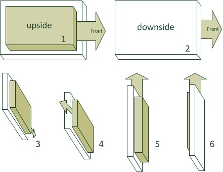
Now we have uploaded the firmware that outputs raw sensors readings (you must have the default calibration.conf). During the calibration, we will move the pixhawk so each of the 6 sides is facing downwards at some point, as shown in the image below:
cd smaccmpilot-stm32f4/src/ivory-px4-hw/test-clientpython sensorsmonitor-calibration.py /dev/ttyUSB0to check that you are getting dataYou should see something like:
205.343 66 IMU_ACCEL_RAW 72 -790 -4210 205.364 66 IMU_MAG_RAW -2216 -2639 7920 205.363 66 IMU_ACCEL_RAW 64 -781 -4217 205.384 66 IMU_MAG_RAW -2199 -2574 8012 205.383 66 IMU_ACCEL_RAW 68 -787 -4229 205.404 66 IMU_MAG_RAW -2191 -2610 7959 205.403 66 IMU_ACCEL_RAW 65 -788 -4219 205.424 66 IMU_MAG_RAW -2169 -2595 7959- Start recording data with
python sensorsmonitor-calibration.py /dev/ttyUSB0 > accelCal1.data(replaceaccelCal1.datawith your own file name) - Immediately after you start recording, move the Pixhawk into each of the positions shown above and keep it there in a steady state for 6-10 seconds
- Once finished, stop recording (
Ctrl+C) - Run the calibration script on the recorded data
./calibration/calibrate.py -s ACCEL -p -v accelCal1.data You will see something like:
reading file accelCal1.data for aircraft 66 and sensor ACCEL
found 1167 records
Using noise threshold of 409.562238209 for filtering.
remaining 671 after filtering
initial guess : avg 9.7076822523 std 0.0881058170084
optimized guess : avg 9.80994055284 std 0.0241489791359
The
avgvalue should be almost exactly 1g, while thestdshould be very small (as shown above). If that is not the case, you have to repeat the calibration
There will also be a plot like this:<define name="ACCEL_X_NEUTRAL" value="49"/> <define name="ACCEL_Y_NEUTRAL" value="-106"/> <define name="ACCEL_Z_NEUTRAL" value="-139"/> <define name="ACCEL_X_SENS" value="2.45582430418" integer="16"/> <define name="ACCEL_Y_SENS" value="2.44793341773" integer="16"/> <define name="ACCEL_Z_SENS" value="2.41664395911" integer="16"/>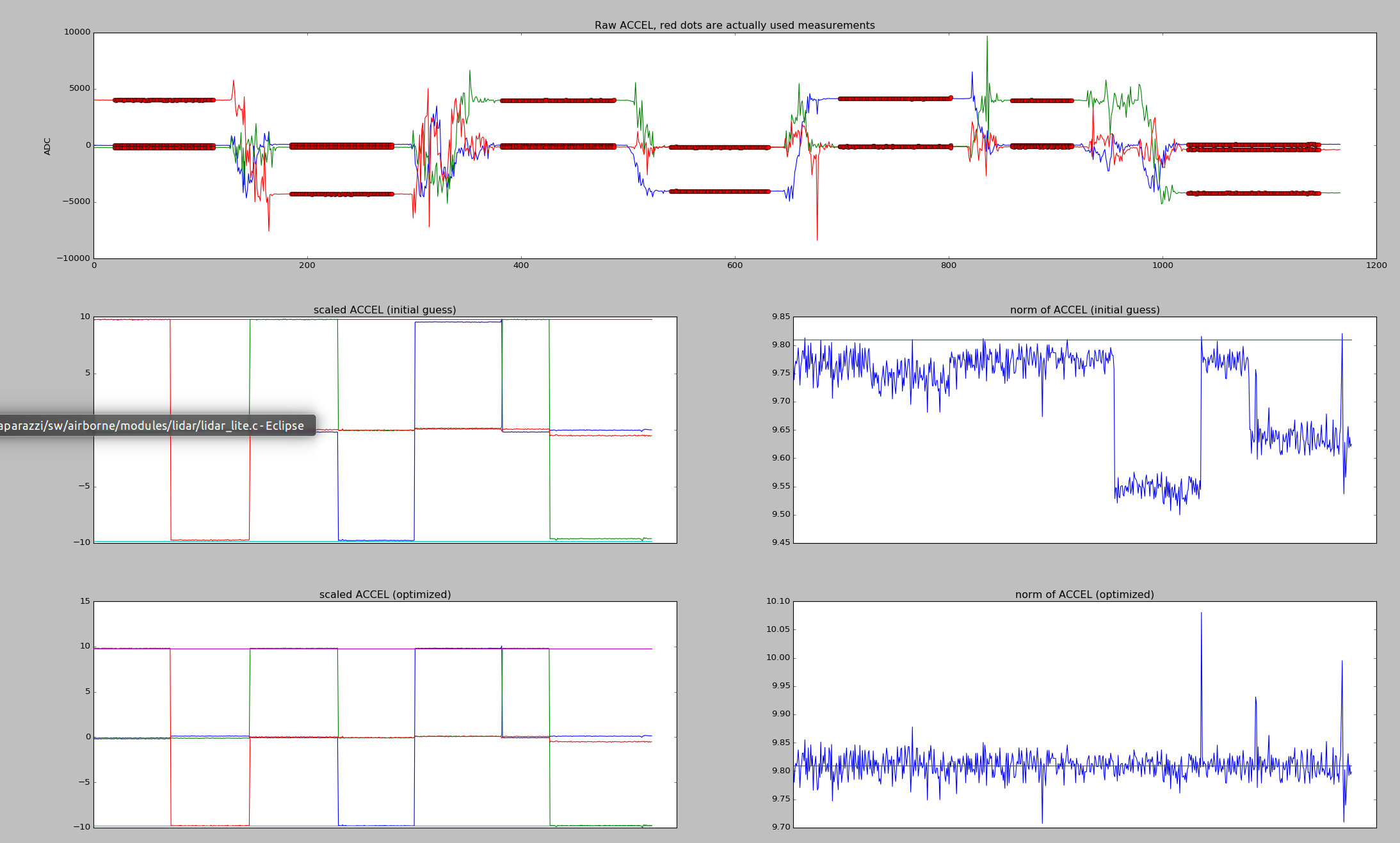
- In the top part you see a plot of our raw accel readings (notice the y-axis scale). We are trying to scale those measurements to be between -1g and +1g. The two plots in the right show the norm of accel, which as you might have guessed by now should be exactly 9.8 m/s^2. If that is not the case, you have to repeat the calibration.
- Copy the accelerometer offsets and scales into your
smaccmpilot-stm32f4/src/smaccm-flight/calibration.conffile in the [calibration.mpu6000.accelerometer] section. The X_NEUTRAL value goes to x_offset, X_SENS goes to x_scale, and so on cd smaccmpilot-stm32f4/src/smaccm-flightmake clean; make flight_echronosto build the flight imagemake upload_flight_echronosto upload the image- Place the Pixhawk on a flat surface and make sure it stays flat
- Start the GCS and verify that the artificial horizon is also almost perfectly flat, something like this:
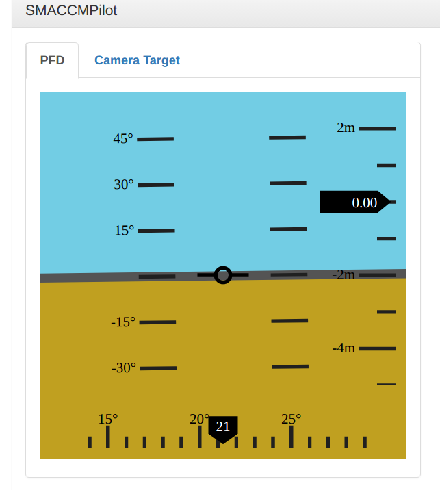 If that is not the case, you have to repeat the calibration
 - Check
http://localhost:8080/sensors_accel.htmland verify that you are reading -9.8 m/s^2 in the z-axis and almost zeros in the other axes, something like this: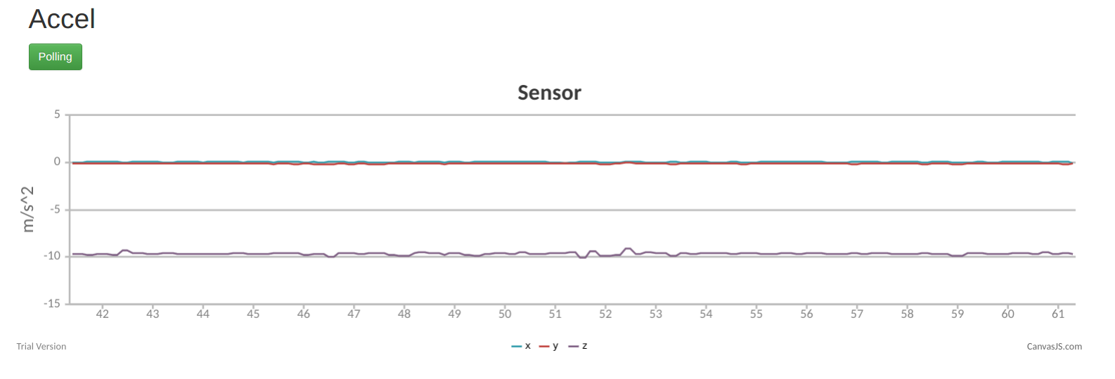
If you are happy with the results, mount the Pixhawk back in the Iris+ to get it ready for the magnetometer calibration
Magnetometer
The goal of the magnetometer calibration is to offset and scale the readings in such a way that the magnetometer outputs a normalized magnetic vector. Why? Because we are using a normalized earth magnetic field vector for heading estimation.
Preparation
It is important to note that all ferromagnetic materials near the mag distort the measurements. So preferably you will do the mag calibration with the mag/autopilot mounted in your frame and as far away from other metal and magnets as possible.
Procedure
First we have to upload all_sensors_ext_mag_test firmware. This firmware is different for the external (HMC5883L) magnetometer. If you want to calibrate for the internal (LSM303D) magnetometer (default), you can skip to step 9.
- Make sure that the
smaccmpilot-stm32f4/src/ivory-px4-hw/calibration.conffile has magnetometer offsets to zero and magnetometer axis scales to1.0(or checkgit diff calibration.confto make sure there are no local changes) cd smaccmpilot-build/smaccmpilot-stm32f4/src/ivory-px4-hwmake clean; make platform-fmu24/px4-all-sensors-ext-mag-test-gencd platform-fmu24/px4-all-sensors-testpython px_uploader.py --port /dev/ttyACM0 image.px4(on Linux; for MacOS, use your own port name)
For the hard-iron calibration, we need to move the magnetometer with all axes around a sphere. Think about it as if you wanted to paint inside of a sphere with the point of the Iris+ (x-axis). HINT: sequentially align the Iris+ as if you were doing the accelerometer calibration, and then in each position rotate the Iris+ slowly all the way around its vertical axis and back. It might need some practice, but fortunately we have to do this calibration only once.
cd smaccmpilot-stm32f4/src/ivory-px4-hw/test-clientpython sensorsmonitor-calibration.py /dev/ttyUSB0to check that you are getting dataYou should see something like:
205.343 66 IMU_ACCEL_RAW 72 -790 -4210 205.364 66 IMU_MAG_RAW -2216 -2639 7920 205.363 66 IMU_ACCEL_RAW 64 -781 -4217 205.384 66 IMU_MAG_RAW -2199 -2574 8012 205.383 66 IMU_ACCEL_RAW 68 -787 -4229 205.404 66 IMU_MAG_RAW -2191 -2610 7959 205.403 66 IMU_ACCEL_RAW 65 -788 -4219 205.424 66 IMU_MAG_RAW -2169 -2595 7959- Start recording data with
python sensorsmonitor-calibration.py /dev/ttyUSB0 > magCal1.data(replacemagCal1.datawith your own file name) - Immediately after you start recording, start with the hard-iron calibration described above
- Once finished, stop recording (
Ctrl+C) - Run the calibration script on the recorded data
./calibration/calibrate.py -s MAG -p -v magCal1.data You will see something like:
Using aircraft id 66
reading file magCal1.data for aircraft 66 and sensor MAG
found 3985 records
Using noise threshold of 3651.05502967 for filtering.
remaining 3965 after filtering
initial guess : avg 0.966739941734 std 0.102544232524
optimized guess : avg 0.997178254747 std 0.0530451037009
The
avgshould be as close to 1.0 as possible, andstdas small as possible too.
And plots like this:<define name="MAG_X_NEUTRAL" value="397"/> <define name="MAG_Y_NEUTRAL" value="-281"/> <define name="MAG_Z_NEUTRAL" value="756"/> <define name="MAG_X_SENS" value="0.388798741374" integer="16"/> <define name="MAG_Y_SENS" value="0.382649033587" integer="16"/> <define name="MAG_Z_SENS" value="0.396648366431" integer="16"/>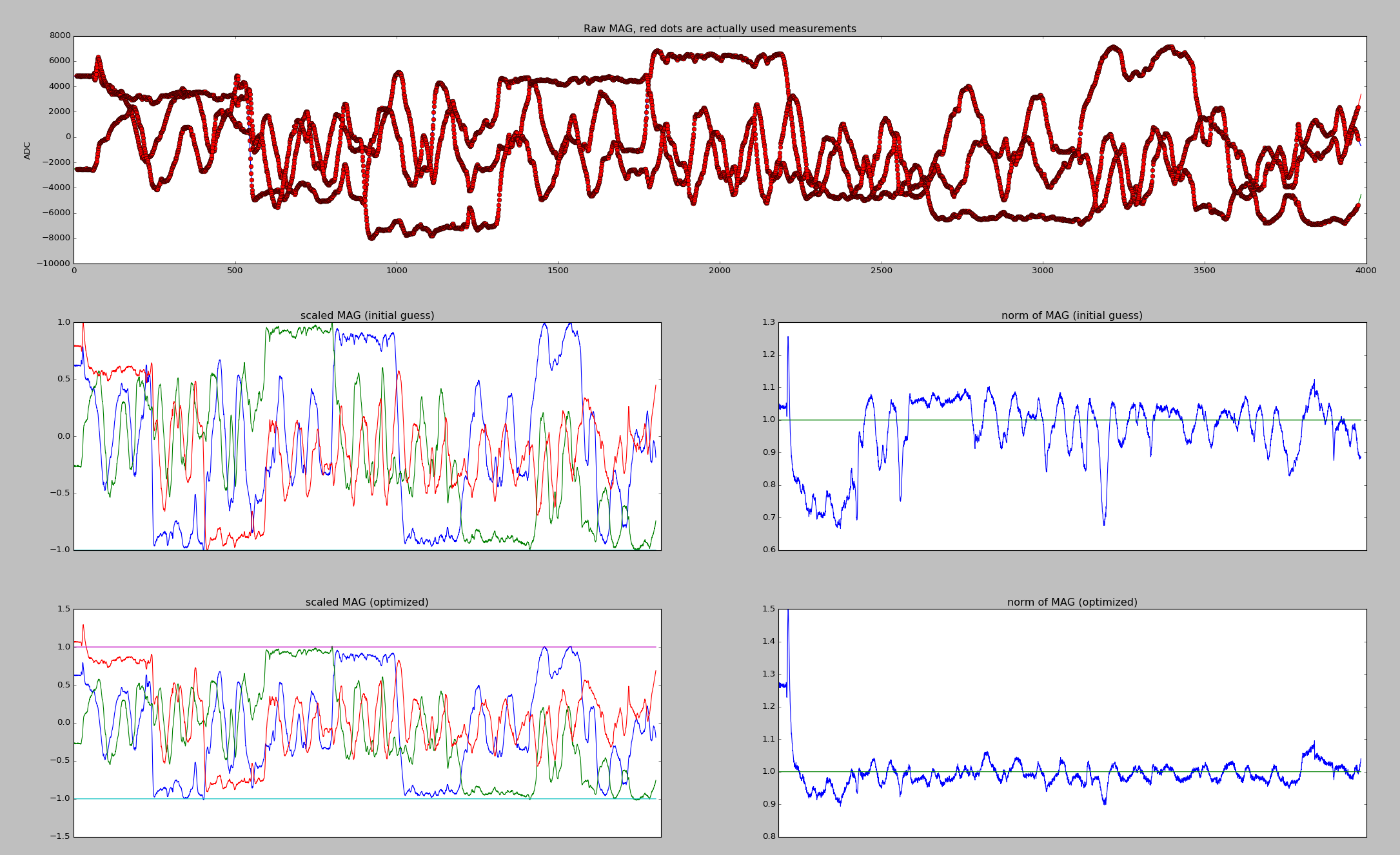
- Notice the two plots at the bottom right: we want the norm of the mag vector to be 1.
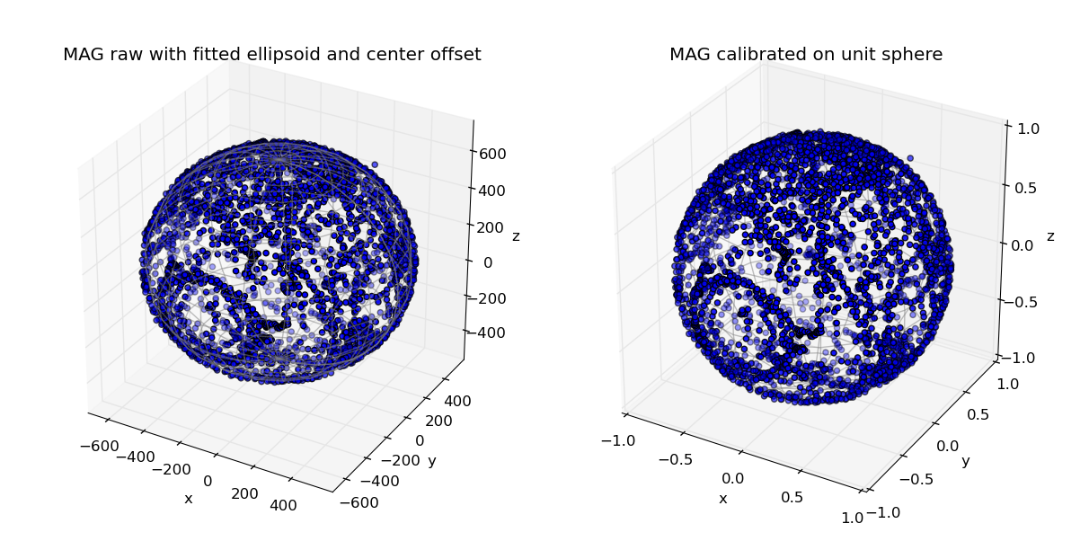 Here we see the measurement points we took. If the sphere is not covered consistently or has holes, it means that you didn’t paint the whole sphere. Note that something like this:
 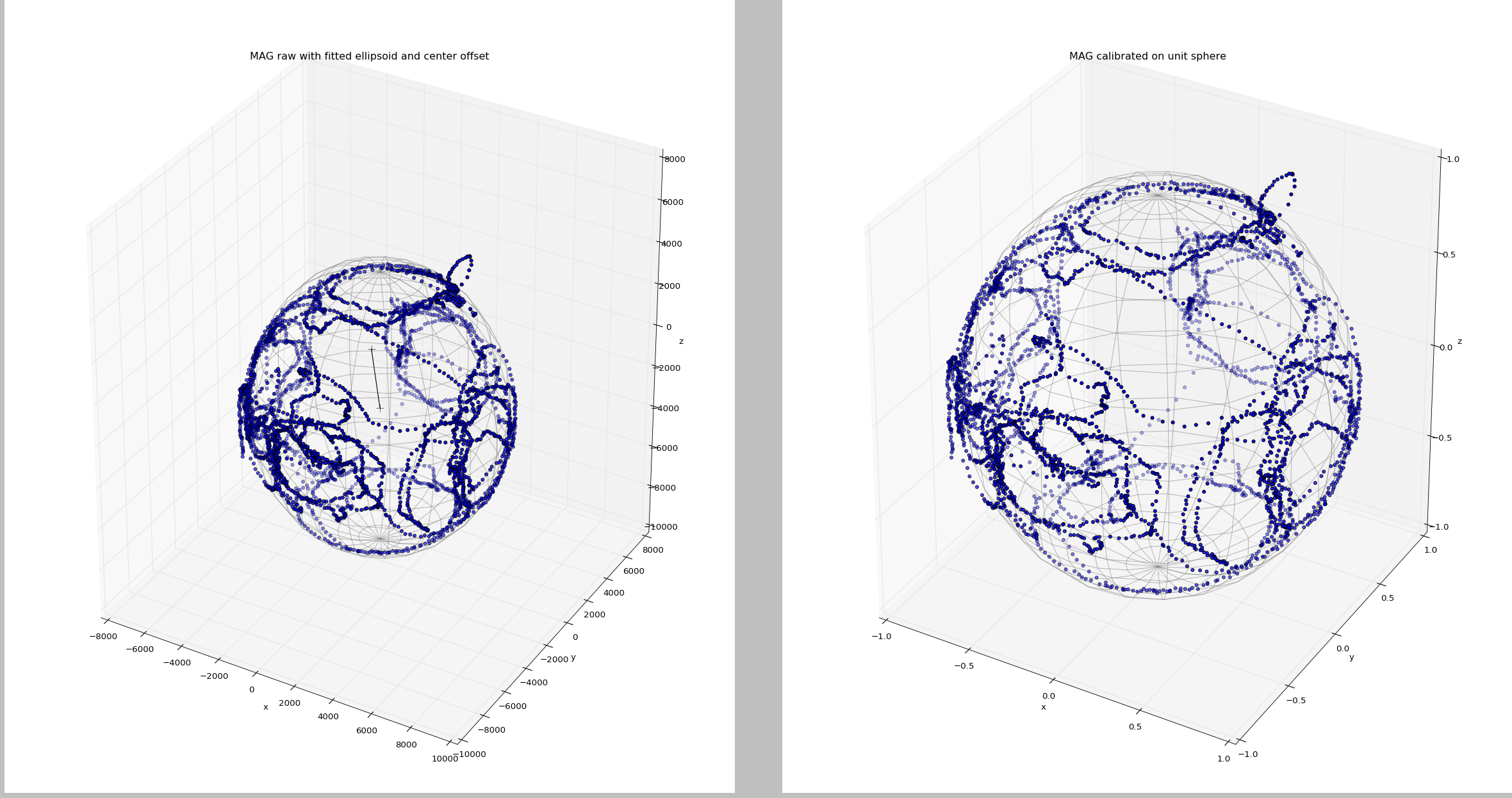 is most likely also fine
 - Copy the magnetometer offsets and scales into your
smaccmpilot-stm32f4/src/smaccm-flight/calibration.conffile in the [calibration.hmc5883l.magnetometer] (external mag) or [calibration.lsm303d.magnetometer] (internal mag) section. The X_NEUTRAL value goes to x_offset, X_SENS goes to x_scale, and so on. cd smaccmpilot-stm32f4/src/smaccm-flightmake clean; make flight_echronosto build the flight imagemake upload_flight_echronosto upload the image- Point the Iris+ towards North (ideally) or to some known heading
- Start the GCS and verify that the heading is stable and points to approximately correct azimuth (NOTE the real vs. estimated heading might differ depending on your latitude). If that is not the case, you have to repeat the calibration.
- Check
http://localhost:8080/sensors_mag.htmland verify that your readings are between -1 and 1 no matter what the orientation of the Iris+ is - Check
http://localhost:8080/sensors.htmland see if your yaw is stable. Try to move the Iris+ left and right and see if you get back to the original heading (at least approximately). If you are happy with the results, you are good to fly