Iris+ modification
SMACCMPilot requires some modifications to the stock Iris+ before it can be used for a stabilized indoor flight.
Parts
Depending on your application (stand-alone vs. full demo flight) you will need the following parts:
Stand-alone flight:
Demo flight:
All Stand-alone flight parts plus:
Optional:
If your quadcopter is not holding heading properly, you will need:
LIDAR-Lite v3
Available here.
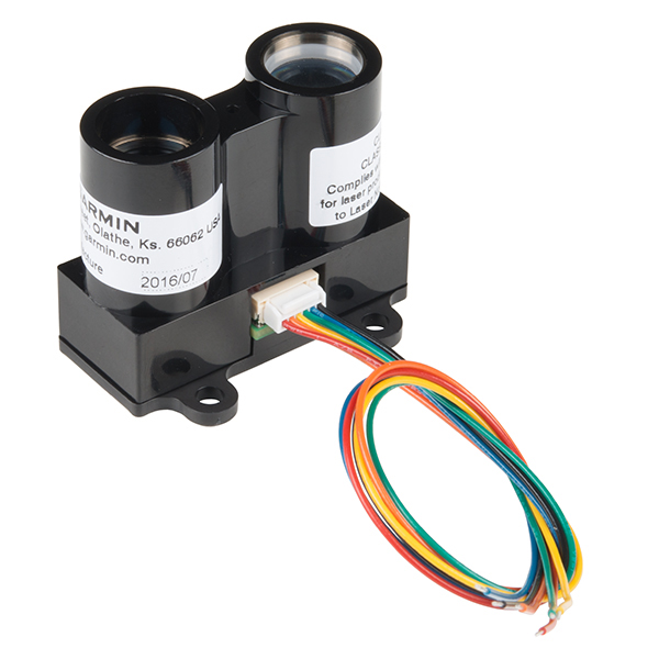
Lidar uses a laser beam to precisely measure distance, and we use it to measure the quadcopter’s altitude. No firmware update is required as the lidar ships ready-to-go.
Mounting instructions are here.
PX4Flow camera
Available here.
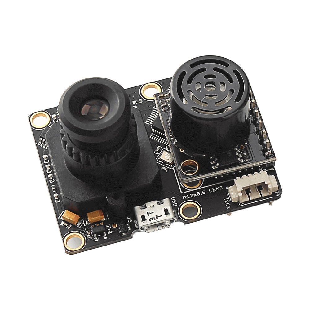
PX4Flow contains a camera and a STM32F4xx microcontroller that calculates optical flow measured in the camera image. The module also contains a gyro, so the flow can be derotated and a sonar for range measurements, so the flow can be measured in absolute units.
SMACCMpilot uses PX4Flow sonar measurements as another input to our altitude estimator, because we want to have redundancy in case one sensor fails. SMACCMpilot doesn’t use the optical flow information at the moment, because there is no postion stabilized mode, but it is one of the possible extensions.
NOTE: no firmware update should be needed, although we noticed that some versions of the PX4Flow ship with firmware that is different than latest stable master. Generally you shouldn’t need to update the firmware, but in case you experience problems, have a look at the wiki page.
Mounting instructions are here.
Pixy Cam
Available here.
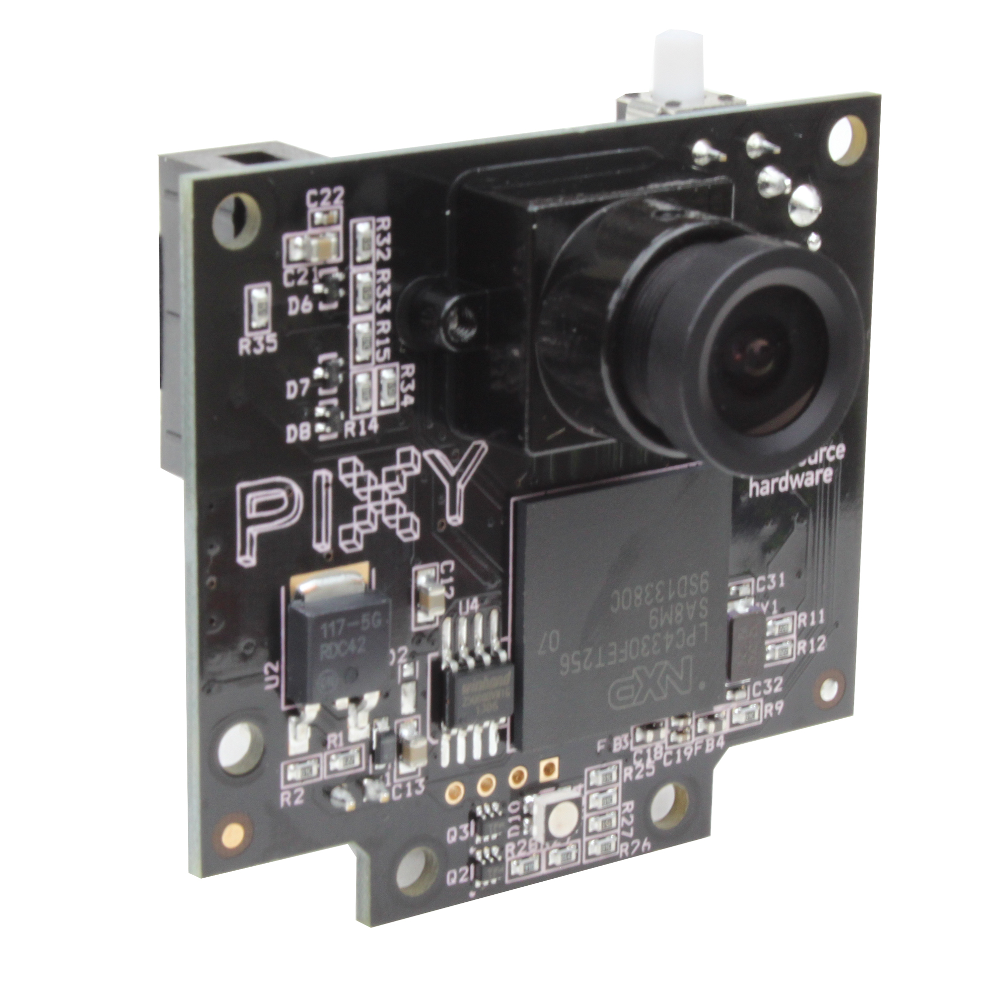
Pixy Cam is optional because it requires using a TK1 as a mission computer. The Pixy cam needs a special firmware: upload firmware-1.0.2beta.hex using the PixyMon app. The camera recognizes targets of a specified color, and can be trained to any color by pressing the button while connected to power.
Mounting instructions are here.
TK1-SOM Module
Available here.
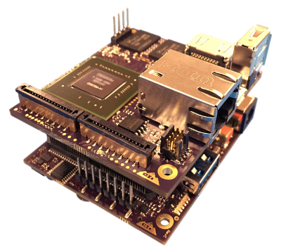
The TK1 serves as a mission computer during the flight, providing communication between GCS and the autopilot, and other high-level functions such as capturing and transmitting video signal from the onboard camera. It runs seL4 and a Linux virtual machine. The TK1 is necessary for a full demo flight.
Mounting instructions are here.
TK1 Daughterboard
The TK1 daughterboard was developed by Data61 and provides CAN, PWM, power management, and more. More info can be found here, and the source files are available on bitbucket.
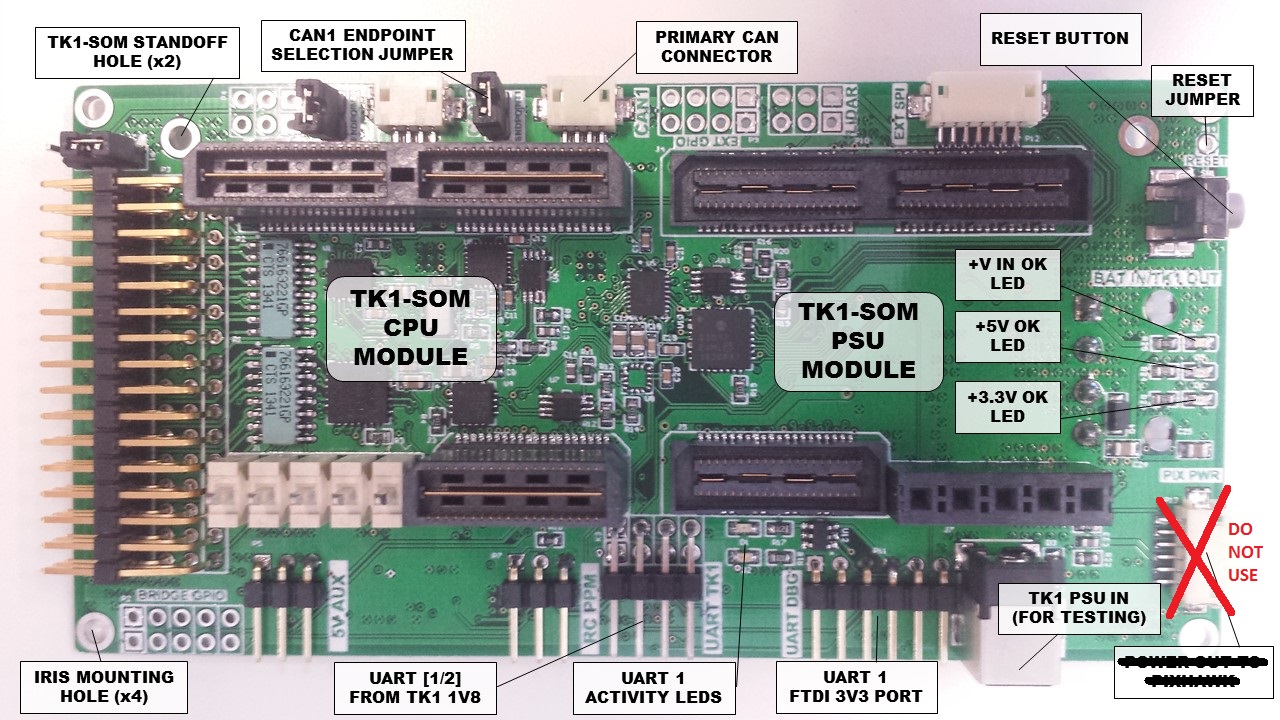
This daughterboard cannot be directly purchased at the moment, but the source files are available so it can be replicated if needed.
Mounting instructions are here.
WiFi dongle
Available here
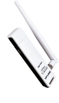
The WiFi dongle is necessary to provide wireless connectivity to the TK1. It is possible to use a different WiFi dongle, but we had good results with the TP-Link N150 Wireless High Gain USB Adapter (TL-WN722N). The dongle plugs into the USB hub.
Mounting instructions here.
USB hub
Available here.
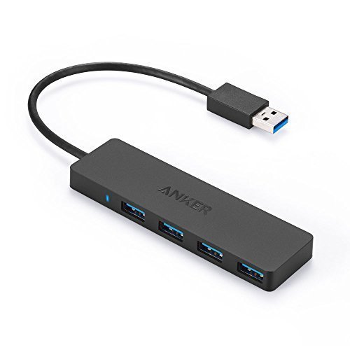
The USB hub goes on top of the TK1 and is necessary for connecting the WiFi dongle and the Pixy cam, because the TK1 doesn’t have enough USB ports. You should be able to use a different USB hub, but we have tested with the Anker 4-Port USB 3.0 Ultra Slim Data Hub.
Mounting instructions are here.
Connectors
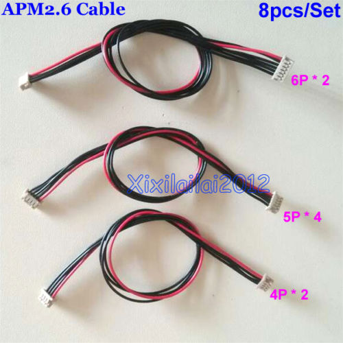
A handful of connectors (we recommend shopping on eBay, as you can buy them very inexpensively)
Tupperware

Best obtained from your local store; the size that works best is *6" x 4" x 2“* (L x W x H). The tupperware contains and protects the sensitive electronics of the mission computer.
External compass
Available on eBay (search for “3DR Compass”).
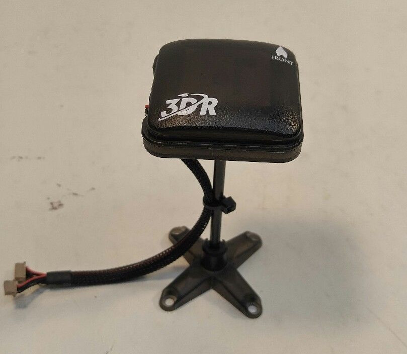
In case of intereference, the heading estimate might not be good even after magnetometer calibration. In this case, you can try using the external compass. This compass is identical to the one hidden in the top cover of Iris+, but it comes on a stand-off so it can be mounted further away from interference.
NOTE: The unit is powered from the GPS connector, so even though SMACCMPilot doesn’t use GPS, you either have to connect both the GPS and I2C cables (follow the instructions here) or solder the I2C VCC to GPS VCC on the compass side.